Using Computational Fluid Dynamic (CFD) Analysis to Inform Design

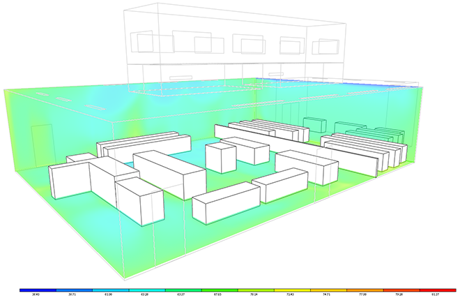
With the transition to Integrated Environmental Solutions – Virtual Environment (IESVE) from Trane Trace as the primary load calculation software, there is a more accessible way to create Computational Fluid Dynamic (CFD) models of spaces. Since MicroFlo, which is the IESVE CFD application, is included in the IESVE program, the rooms built for energy modeling can be used in the CFD analysis without creating a separate model. The CFD model can then be updated as the energy model changes.
CFD models can be created for important rooms in design that benefit from the analysis. Although not taken as exact measurements, the calculations give us an opportunity to view what is happening with the air in the room. MicroFlo allows us to check airflow speeds and direction to inform design decisions. The model can show how far the air is reaching into the room from the diffusers. This allows us to check diffuser placement to ensure comfort for occupants. This same concept can be implemented for looking at the humidity and temperature distribution throughout the room.
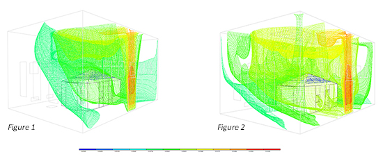
One project this was applied to was a historical landmark study. The room was a double height space with a central display for visitors to view. The doors to the exterior allow for infiltration into the space. The mechanical system includes two supply grilles on the same wall and two floor return grilles placed near the display. An additional ceiling circulation system that creates a ceiling fan effect is located in the attic. This circulation system is currently not operating.
The CFD analysis allowed us to create visuals to demonstrate the benefits of repairing the ceiling circulation system. CFD models with the system on and off were created to show comparisons of the room conditions. With the system off, the increased temperature and humidity of the system was apparent in the stratification of the room (Figure 1). The infiltration from the doors impacted the humidity levels of the room especially during the summer months. The circulation system on showed a better distribution throughout the room (Figure 2). Based on the analysis, it was recommended that the circulation system be repaired, and images of the results were used to explain the design in the report.

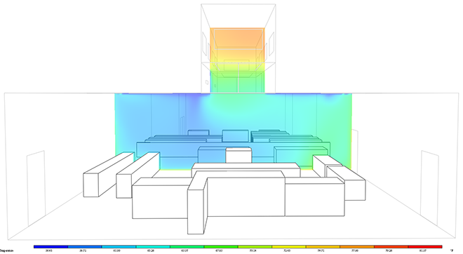
In another project application, CFD was used to view how air was dispersing across the room from the diffusers and the resulting temperature gradient. Due to a clerestory in the center of the room, the initial diffuser layout had linear diffusers near the perimeter walls of the room. The air flow and temperature analysis showed that occupants sitting near the middle of the room under the clerestory would have an inadequate amount of supply air reaching them to keep the temperature at a comfortable level. Diffusers were then added to the side walls of the clerestory to increase the amount of conditioned air reaching the center of the room. The analysis showed that the temperature gradient across the room maintained better comfort levels (Figure 3). With the CFD model showing the benefits of the additional diffusers, a new mechanical layout was coordinated with architecture and other impacted disciplines.

For projects with important air distribution spaces, CFD can be an informative tool in the design process. It allows for a check of building conditions and system layout that would be hard to visualize. It is a visualization tool that can help the designers and clients understand the system.

Comments